
I was at the IIAR convention a few weeks ago which afforded me the opportunity to do something I’ve long wanted to do: Get a chance to ask representatives from Danfoss, Hansen and R/S Parker to give me their thoughts on properly labeling Compound Valve and Multi-Valve platforms. I am going to use the Danfoss valves as an example for this article, simply because I have lots of diagrams and pictures around based on past experience with them.
The idea of all of these platforms is that you basically get a valve-station in a single valve body. The valves take up less room, require less welding, etc. I don’t have any arguments with any of that: my issue is how I am seeing them referenced on a P&ID and in SOPs.
Let me give you an example:
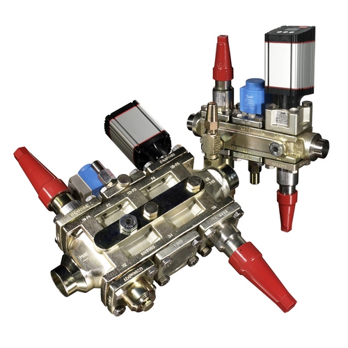
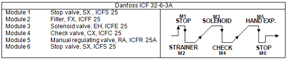
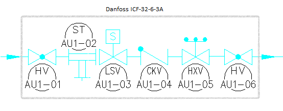
The valve we are going to talk about is a Danfoss ICF-32-6-3A. It is a fairly common configuration replacing a traditional liquid valve-train.
What I am seeing in the field is that this is represented in the field on the P&IDs as something like this:
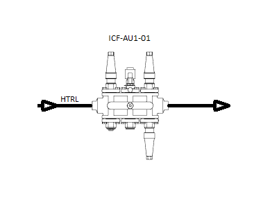
In this situation, the entire compound valve is represented by a single tag. This results in SOP steps like this:
1) Close the liquid stop valve on ICF-AU1-01.
That step requires the operator to figure out which of the valves is the liquid stop valve. The correct answer is the first module or M1. We could write the stop to say so explicitly:
1) Close the liquid stop valve (Module 1) on ICF-AU1-01.
However, this step still requires the operator to identify the module. Most of the multi-valves have the Module (or port) number stamped on the valve but paint and insulation could get in the way of that.
What I would prefer to see is a more traditional valve labeling/tagging where each valve module/port is explicitly labeled/tagged. One way to do this while keeping with the same type of P&ID display is as follows:
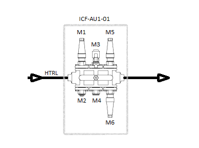
This would let us change the SOP step to something like this:
1) Close the liquid stop valve on ICF-AU1-01-M1.
Of course, we could always reference each component of the valve with the more traditional names and tags such as :
- HV-AU1-01 : Hand Valve (Stop in this case) on the air unit.
- ST-AU1-02 : Strainer on the air unit.
- LSV-AU1-03 : Liquid Solenoid on the air unit.
- CKV-AU1-04 : Checkvalve on the air unit.
- HXV-AU1-05 : Hand Expansion valve on the air unit.
- HV-AU1-06 : Hand Valve on the air unit.
This might clutter up the drawing a bit, but something like this would be perfectly acceptable as well:
Whichever method you choose, the performance basis is going to be what your operators understand. When introducing these new types of valves, a little bit of training and employee participation goes a long way!
