Region 7 Ammonia Safety Day

If you are within a couple hundred miles of Kansas City, Kansas it’s worth attending the 7th annual Region 7 Ammonia Safety Day which is held at the Kansas City Community College on May 28th, 2014.

More information including the schedule and enrollment link can be found at GCAP’s website.

Of special interest this year is a presentation by Lucy Tyler of the CSB on a large NH3 release in Alabama. OSHA and the EPA will be presenting as well.

Posted in Community Involvement, Compliance, CSB, EPA, Operator Training, OSHA | Tagged , , , , , | Comments Off on Region 7 Ammonia Safety Day

Here’s a change that doesn’t require a Formal MOC!

I am sure many of my PSM friends have noticed my lethargic posting rate at the blog over the past year or so. I’ve been running all around the country helping people with their PSM programs through Audits, PHA’s and Training at a breakneck pace during that time as the Director of Compliance for Garden City Ammonia Program.

I have spent four years there working with the fine staff building and improving the PSM program and services they offered. In that time I’ve worked with some wonderful people at GCAP and earlier today, with a heavy heart, we both decided that our future paths were going to diverge.

I wish the best for the GCAP staff as they continue to provide world-class training to operators around the country. It was an honor and a privilege to work with the staff, some of whom I’d like to acknowledge directly:

Randy Williams – A true visionary who has done more for this industry than he’ll likely ever get credit for. The creator of GCAP and a legend in his own time.

Jeremy Williams – A talented and knowledgeable man who, I believe, will grow GCAP into something uniquely his own in the future.

Steve Rucker – The Director of the Boiler division at GCAP that continues to impress us all with his ability to grow and meet challenges. I expect great things from the Boiler division in the future.

Tyler Ramos – One of the most talented instructors I’ve ever met and a genuinely nice guy.

Kristen, Dolly, Amber and Rachel – The office staff that tried to keep me sane when I traveled 40+ weeks a year. They always had my back and I am grateful for their diligent work behind the scenes that makes everyone else look so good.

Bret Geier –  Our maintenance man who keeps his attention on the little things while the instructors get to keep their heads in the clouds.

Working with talented people makes “work” worth doing and I’ve definitely had quite an experience over the past few years. I hope for, and expect nothing less than, continued success for GCAP in the future.

The real joy, of course, was meeting all the students that passed through our classes over that time. I’ve made some great friends and worked with some incredibly devoted and talented colleagues from the world’s best Ammonia Refrigeration users. It was a great honor to be a small part of their careers.

Last, but certainly not least, I’d like to thank my wife Diane who has been enormously patient during this wild ride!

I am not sure where I go from here – but I think a little bit of a vacation is in order. Hope to see you all again soon!

Posted in General Information, Management of Change | Tagged | Comments Off on Here’s a change that doesn’t require a Formal MOC!

Welcome 2015!

I’ve been slow in my posts recently due to an incredibly hectic schedule in both my professional and personal life and for that I apologize. I’ll see what I can do to improve the post rate in 2015. Remember, there are usually more posts at GCAP’s ChemNEP site than here! Here’s a roundup of the last year:

In 2014, I continued to work as GCAP’s Director of Compliance Services teaching classes all over the country as well as performing PHA’s and compliance audits for those we have a training relationship with. While I was hard at work on the road, GCAP continued to improve back at the home office. The huge expansion is almost complete and the PSM facility – including a classroom specifically designed just for PSM – has been completed. I taught the first class there in December and it’s fantastic!

The GCAP staff continues to set the standard for training excellence. It’s an honor to work with the other instructors: Randy Williams, Jeremy Williams, Tyler Ramos, Anthony Verdugo, and Steve Rucker. You can’t forget the office staff either: Rachel, Dolly, Amber and Kristen – they keep us on schedule and make us look good with their behind-the-scenes preparation.

We’re adding new instructors in 2015 as well, so I am looking forward to working with the new talent. I can’t divulge any of those coming on board except one: A personal friend named Ethan. Ethan is an extremely bright and talented individual with the personality of a rock star. He’s going to make a great instructor and I look forward to seeing him develop into an auditor and consultant as well.

The PSM text book we wrote for GCAP’s PSM classes includes a PSM program template and both the book and the template have been continuously improved through 2014. The New Year will see a new version of the book and we’ve instituted a Google Drive for our PSM students so they always have the newest version of all the templates at their disposal. Many customers use the GCAP template as the basis for their PSM program and we get the benefit of their refinements to it. This year alone we added a Car-Seal program, and extensively modified the MOC and Incident Investigation elements due to customer input/feedback. The SOP template continues to improve as well due to field work. The continuous improvement aspect of our work continues to be the most important part of it!

In my personal life, it’s been busy as well. My first grandson was born adding to my three granddaughters. My son moved to Kansas and it’s good to see him regularly now. My consistent traveling partner, friend and colleague, Josh Latovich headed back into private industry at the end of the year. I’m sad to see him go – he’s one of the best PSM guys in the country – but I am also immensely proud of him and wish (and expect) nothing but the best for him in his new venture.

My wife Diane continues to keep things squared away on the home front. She’s still working in Retail Management, but I think the crazy hours are finally getting to her and she may actually slow down in 2015. Who am I kidding? She’s the most devoted workaholic I know! Thanks, Diane, for providing a sense of normalcy (as best as can be accomplished) under absurd circumstances. You always rise to the challenge!

Back in the professional realm, I logged 75,000 miles in air travel alone and was on the road a little over 250 days last year! That pretty much means a life of hotel rooms and restaurants. I’m not complaining, but it sure is nice to get home occasionally to see the wife, kids and grand-kids.

I am constantly asked why I do this to myself – travel constantly and spend so much time away from family and friends. Often I joke that it’s the “Rock-N-Roll” lifestyle of the PSM professional, but that’s really a deflection.

Here’s the real answer: To a large degree, my family and friends are the people I am on the road FOR.

True, I travel for work. But my work is also my passion. I get to work with some of the brightest, most decent, honest and sincere people in the business. When I get to a facility and see a student and get to see how they are applying the concepts we’ve taught them – that is the best reward I can imagine. When I can help people solve problems they’ve struggled with for years, that’s a great feeling. When I see a new way of dealing with a problem, and get to bring that solution to new people – well, you can’t do that sitting in the office! You see, these people in the industry are my family and friends too. They are what makes this all worth-while.

So, Thank YOU! So many of you continue to inspire and teach me as well: Dave, Chris, Pete, Alan, Thomas, James, Bryan and so many others. Keep up the good work – it’s a privilege to be part of your continuing success!

I don’t plan on slowing down in 2015. I hope to see you – either on the road or when I am teaching at GCAP’s new PSM facility!

Posted in Community Involvement, General Information, Standardization, Uncategorized | Tagged , | Comments Off on Welcome 2015!

Relief Systems – Understanding Design and Design Basis

In compliance audits all over the country, we’re finding that the requirements for documenting the relief systems are not being met in many PSM programs. How bad is the situation? About 1/3rd of the relief documentation we see shows that the relief system DOES NOT meet the chosen design basis. About 90% of the remaining relief documentation doesn’t address the chosen design basis enough to make a case either way.

First, let’s take a minute to make sure we understand the difference between design and design basis.

Design Basis: The design code, standard, or RAGAGEP chosen to serve as the requirements. You can think of it as the conditions for success.

Design: How the facility actually met the Design Basis. This should include the “work” behind the design – the measurements, calculations, etc.

Let’s say we chose IIAR2-2008b as our Design Basis. Your documentation is likely limited to some spreadsheets provided by an engineer that shows the measurements and calculations that the engineer did to show that the piping design met the RAGAGEP.

That’s great. We definitely need that and that’s why you hired an engineer in the first place. But there is more to meeting the design basis than doing advanced math! You need to include an explanation of how all the other requirements were met. To give you an idea, of the sorts of things that you would need in your documentation for just IIAR-2 2008:

  • (11.1.1) The relief system meets ANSI/ASHRAE 15-2007 Section 9.4 [ref.4.1.4] excepting section 9.4.3
  • (11.1.2) If stop valves exist downstream of a relief device, that they are locked open when in service. Reference to a car-seal program to control the valve position.
  • (11.1.2) If stop valves exist downstream of a relief device, the relief calculation includes the pressure drop across the stop valve. Reference to the engineering calculations to back this up.
  • (11.1.3) Relief valves are installed as near to equipment being protected as possible.
  • (11.1.4) Unless hydrostatic the relief is connected at the highest practical point.
  • (11.1.5) If installed in refrigerated spaces, precautions have been taken to prevent moisture buildup in the valve or relief line. Reference maintenance procedures or PHA section as necessary.
  • (11.1.6.1) The relief valves are set to function at a pressure equal or lower than the design pressure of the protected system.
  • (11.1.6.2) If installed, rupture discs are set to function at a pressure equal or lower than the design pressure of the protected system.
  • (11.1.6.2) If installed, rupture discs conform to Section VIII, Division 1, ASME Boiler and Pressure Vessel Code.
  • (11.1.6.2) If installed, rupture discs ahead of relief valves are at least as large as the relief valve inlet.
  • (11.1.6.2) If installed, rupture discs have provisions in place to detect pressure buildup between the disc and a relief valve. Reference to the maintenance procedure (such as daily walk-through) and any automated systems in place.
  • (11.1.7.1) Pressure relief valves settings are set by the manufacturer.
  • (11.1.7.1) Pressure relief valves are marked to conform with Section VIII, Division 1, ASME Boiler and Pressure Vessel Code.
  • (11.1.7.2) Rupture discs are marked to conform with Section VIII, Division 1, ASME Boiler and Pressure Vessel Code.
  • (11.1.7.3 & 11.1.8) The capacity of the relief devices are stamped on the valve or available.
  • (11.2.1) Pressure vessels relief protection complies with Section VIII, Division 1, ASME Boiler and Pressure Vessel Code
  • (11.2.2) If a pressure vessel is capable of being isolated by stop valves, it must have overpressure protection.
  • (11.2.3) Reliefs are sized in accordance with IIAR2-2008b 11.2.7. Reference to the engineering calculations to back this up.
  • (11.2.5) Vessels with internal volume of 10 cubic feet or greater are equipped with three-way valves and dual pressure relief valves or a single valve if the vessel is on the low-side, can be pumped out and the other vessels are protected in accordance with IIAR2-2008b 11.2.7.
  • (11.2.6) When pressure is relieved into other vessels, that the back pressure is taken into account and that the affected vessel has its reliefs sized for the combined capacity of both vessels. Reference to the engineering calculations to back this up.
  • (11.2.7) The discharge capacity of the relief device meets the requirements of this section. Reference to the engineering calculations to back this up.
  • (11.2.7) When one relief device serves multiple vessels, the discharge capacity of the relief device meets the requirements of this section. Reference to the engineering calculations to back this up.
  • (11.2.7) When combustible materials are used with 20ft of a pressure vessel, the modified formula is used. Reference to the engineering calculations to back this up.
  • (11.2.8) The rated discharge capacity of the relief valve was determined in accordance with Section VIII, Division 1, ASME Boiler and Pressure Vessel Code. Reference to the engineering calculations to back this up.
  • (11.2.8) The capacity marked on the nameplate of the relief device is expressed in lb/min air or in standard ft3/min (SCFM) of air at 60°F
  • (11.2.9) The rated discharge capacity of rupture discs is calculated with the equation in this section. Reference to the engineering calculations or manufacturers documentation to back this up.
  • (11.2.9) Provisions to prevent plugging the piping when the rupture disc relieves are present.
  • (11.3.1) No stop valves are present on the inlet or outlet piping of the reliefs with procedures in place conforming to ASME Boiler and Pressure Vessel Code Section VIII Appendix M. Reference to the procedures if applicable.
  • (11.3.1) The size of the inlet piping to a pressure relief device is not less than the inlet size of the pressure relief device.
  • (11.3.3) Relief piping conforms to IIAR2-2008b 11.3.3, 10.2.1.5, 10.2.1.6, 10.2.1.7, and 10.2.1.8.
  • (11.3.4) The size of the relief pipe is not less than the outlet size of the relief device.
  • (11.3.4) For headers, relief piping is sized to accommodate all the relief devices that are expected to discharge simultaneously at the lowest pressure setting with consideration given to pressure drop in all downstream piping. Reference to the engineering calculations to back this up.
  • (11.3.5) Where piping or components may contain liquid that could be isolated during operation or service, IIAR2-2008b 11.4 for hydrostatic protection is also applied.
  • (11.3.6) All atmospheric reliefs relieve to the outdoors.
  • (11.3.6.1) The maximum length of the discharge piping is determined by the method in IIAR2-2008b, Appendix A. Reference to the engineering calculations to back this up.
  • (11.3.6.2) Atmospheric relief piping has provisions for draining moisture. Reference to maintenance procedures.
  • (11.3.6.3) The relief point of a relief device to the atmosphere is 20’ or more from any window, ventilation intake, or personnel exit.
  • (11.3.6.3) The direction of discharge is vertically upwards.
  • (11.3.6.4) The discharge from pressure relief devices is 15’ or higher above the adjacent grade or roof level and arranged to avoid spraying of refrigerant on persons in the vicinity. Reference to PHA as necessary to deal with catwalks and platforms.
  • (11.4) This section is applied when equipment or piping sections are isolated manually or automatically.
  • (11.4.1) Only trained technicians taking all necessary precautions to prevent overpressure due to hydrostatic expansion will manually isolate equipment. Reference to training, LO/TO program, written SOPs, etc.
  • (11.4.3) Equipment or piping that can be isolated automatically is protected by a hydrostatic relief device.
  • (11.4.3) Hydrostatic relief devices are not used as shut-off valves.
  • (Appendix A) Relief design is calculated to conform to this section.
  • (Appendix E) Relief design for positive displacement compressors is calculated to conform to this section.

We like to cover all these things in a single narrative with appendices for engineering work. You can do this any way you like as long as you address the requirements of your chosen RAGAGEP. One method is to use GCAP’s IIAR2-2008b RAGAGEP Audit Checklist provided for all GCAP PSM students.

Posted in Compliance, Good Engineering Practices | Tagged , , | Comments Off on Relief Systems – Understanding Design and Design Basis

What’s the deal with Valve torque?

A common question I get is whether or not flanged and bonneted valves need to be torqued when they are installed. Unfortunately, many of these questions are due to OSHA citations – Ideally you want to answer this question BEFORE the OSHA inspection.

The short answer is: Yes, you need to torque valves and bonnets to the manufacturer’s recommendations when you install them.

 The long answer begins with a little history…

The 2005 version of IIAR-3 (Valves) section 5.8, states: “The applicable tightening torque values for the valve bonnet, flanges and other pressure-containing attachments to the valve shall be specified by the manufacturer and made available on request.”

Valve manufacturers went ahead and complied with this and every major valve manufacturer that we’re aware of published torque recommendations. The IIAR revised their wording in 2012 to “The applicable assembly and installation procedures for the valve bonnet, flanges and other pressure-containing attachments to the valve shall be specified by the manufacturer and made available on request.” However, the valve manufacturers had ALREADY posted the torque recommendations.

For one example, R/S Parker, see page 216-218 of the link below:

R/S Parker Valve Catalog

That link would be the “applicable assembly and installation procedures,” right? Even the current version of IIAR-2 states that: “10.5.1 Valves (or flange sets) with specialized tightening requirements shall be installed according to manufacturer’s instructions.”

PSM also requires us to adhere to manufacturer’s instructions:

1910.119(j)(6)(ii) ​ ​Appropriate checks and inspections shall be performed to assure that equipment is installed properly and consistent with design specifications and the manufacturer’s instructions.

In my opinion, and based on citation history, the belief that valve torque is NOT required is unsupportable. If the valve manufacturers removed all their torque requirements from published documents, then it’s possible the issue could be avoided. But honestly, that’s exactly what they are trying to do – Avoid the conversation. It’s really infuriating that the same people that wouldn’t think of installing a new head on their hot-rod without a torque wrench are the people that usually give you the most grief about valve torque.

The real question is: Is the flange or bonnet torque important? The answer to that is undeniably: Yes.

Over-torqueing pinches gaskets making leaks more likely and extreme over-torqueing on bonnets can warp them to the degree that it impairs the function of the valve or regulator.

We should torque the flanged valves and bonnets to manufacturer’s specification not because PSM tells us to, or because the IIAR tells us to, or even because the manufacturer tells us to. We should the flanged valves and bonnets to manufacturer’s specification because it is the right thing to do.

p.s. Previous discussion and citation at this link: https://taocompliance.com//?p=380

p.p.s. You can’t torque old bolts reliably. Once you’ve torqued the bolt, you don’t go back and torque it again since the act of tightening a bolt actually stretches it minutely. Lubrication on bolts drastically changes the actual bolt tension for a given torque – you shouldn’t lubricate bolts that you are going to torque unless the torque specification specifically tells you to. Unless stated otherwise, torque specifications are assumed to be dry, clean and new threads.

Posted in Compliance, Contractors, Good Engineering Practices, Mechanical Integrity | Tagged , | Comments Off on What’s the deal with Valve torque?

EPA RMP Executive Summary

As part of GCAP’s PSM course, we pull the publically available RMP from RTKnet.org for each facility in the class. We’ve seem some strange things in the Executive Summary and wanted to share some guidance on what exactly should and should not be there.

First, let’s look at the most common mistakes:

1) Misunderstandings of Executive Summary: The Executive Summary is meant to be a quick synopsis of the RMP filing, not a brief summary of the executives at the facility. Seriously, a facility had actually put mini-resumes of the executives at the facility in their executive summary.

2) Long, rambling consultant boilerplate: The Executive Summary is supposed to be brief and include only the required information.  Reading some of the Executive Summary’s, you would think that the consultants were paid by the word.

3) The OCA or Offsite Consequence Analysis: While this information was originally required, the law was changed in 2004 to remove this requirement due to National Security concerns. As explained by the EPA:

“A summary of the off-site consequence analysis (OCA) for the worst-case and alternative release scenarios(s) is no longer required to be included in the Executive Summary. While the RMP rule originally required that the Executive Summary briefly describe the OCA for worst-case and alternative release scenario(s), EPA amended the RMP rule in 2004 to remove this requirement because of security concerns. Your Executive Summary should not describe nor include information concerning your worst case or alternative release scenarios.” —-EPA 555-B-09-001

4) Misunderstandings of “Planned changes to improve safety”: Occasionally, you will see someone like EVERY PHA, II, CA and MI recommendation in the system and the status of that recommendation.  The EPA says they expect you to list the following:

“..any upcoming events such as training, installation of new mitigation or control equipment or technology, organizational changes, etc., that will improve safety at your facility. —EPA 555-B-09-001

Usually you can simply provide a statement such as “Through our ongoing implementation of the PSM/RMP program, ABC Company looks continuously for possible ammonia refrigeration system changes to improve safety in our facility.

What should the Executive Summary include? First, let’s look at the purpose of the executive summary:

“The Executive Summary must include a brief description of your facility’s risk management program. You determine the length; it may be as short as two or three pages or, if you have many processes, it may need to be longer. You should view the Executive Summary as an opportunity to communicate in your own words the nature of the risks posed by your facility to your community and to explain what you have done to minimize those risks. The summary can be an excellent vehicle to display the effort and resources your facility has put into its accident prevention program. —EPA 555-B-09-001

Here is the information actually required in the Executive Summary:

  1. The accidental release prevention and emergency response policies at your facility. Describe your facility’s overall approach to chemical safety. You may want to include any corporate policies (if applicable) and an overview of senior management commitment to safety and implementation of safe procedures.
  2. Your facility and the regulated substances handled. Provide a description of your facility so that the public has a clear picture of the facility, its processes, and products. Describe the primary activities at the facility (e.g., manufacturer of polyethylene, pulp mill, etc.) and the regulated substances used.
  3. The general accidental release prevention program and chemical-specific prevention steps. You may wish to mention the rules and regulations with which your facility complies, such as the OSHA PSM rule. You should also highlight practices that you believe are important to your prevention program. The steps you list may be either technological (e.g., backup systems) or procedural/managerial (e.g., improved maintenance or training).
  4. The five-year accident history. This should be a written summary; for example, “We have had five accidental releases of chlorine in the past five years; the largest release was 1,500 pounds. No one offsite was injured, but several houses were evacuated as a precautionary measure during the October 2005 and May 2006 releases.”
  5. The emergency response program. Briefly describe the elements of your response program. These may include coordination with local emergency responders, training received by personnel, drills conducted by your facility, public notification and alert systems, as appropriate
  6. Planned changes to improve safety. List any upcoming events, such as training, installation of new mitigation or control equipment or technology, organizational changes, etc., that will improve safety at your facility.

Posted in Compliance, EPA | Tagged , | Comments Off on EPA RMP Executive Summary

Lessons Shared #2 – “That policy is for other people…”

This post is part of a series on Lessons Shared

This incident is about a common problem in PSM plants: Some people don’t think the rules apply to them.

This story is from a friend who works as a refrigeration contractor. Many smaller facilities lack their own qualified and experience maintenance staff and they hire contractors to do basic maintenance on their systems such as changing oil filters and equipment inspections. My friend had a contract with a company to stop by twice a week and walk through their mechanical room; taking readings and doing basic preventative maintenance.

One day, after he was finished with his work in the mechanical room, he walked out into a hallway and saw a young man on a ladder with a sawzall. The young man was in the process of cutting into a 2” Ammonia High Pressure Liquid line. My contractor friend quickly stopped him – thankfully before he managed to cut through the pipe wall. The young man had no idea what was in the pipe and was not aware how close he came to dying.

How did this situation happen?

It turns out that the Plant Manager had hired the young man (a golfing buddy’s son who was home on break from college) to do some little projects around the plant. The Maintenance Manager had been bugging him about his backlog of work so the Plant Manager took it upon himself to get rid of some of the projects, including a project that involved removing some abandoned water piping. He had told one of the maintenance workers to “tag the pipes you want removed with some fluorescent orange spray paint,” and that’s exactly what happened.

The only work instruction given to the young man was “Go cut out all the old piping. It’s been marked orange so it’s easy to see.” It shouldn’t be surprising that the young man saw the orange High Pressure Liquid Ammonia piping and thought that this was some of the piping to be removed. There was no safety briefing concerning the hazards in the area. There was no training on the location of safety showers, plant alarms or evacuation routes. There was no contractor paperwork.

Why? The plant manager didn’t go through the usual procedure because he thought this was just a little project that would only take a few days. He also explained that the young man wasn’t supposed to be working on the Ammonia system so he didn’t think that PSM applied to him. After all, he reasoned, this is just a college kid making a couple bucks while on break! He also said that he was the Plant Manager – and “those rules were put there to control hourly people, not management!”

It’s not uncommon to find these situations where management thinks that they are above the system and not part of it. It usually happens in elements such as Training, Operating Procedures, Contractors and Management of Change. On the other hand, there are a lot of experienced operators who think the same thing about SOPs: “They are there for the new guy, not for me!”

PSM policies and procedures are put there for EVERYONE who could affect, or be affected by, the process. While it’s possible to have different rules for different people, these different rules must be analyzed in the Process Hazard Analysis.

Please use this story to talk to your maintenance staff about the VERY REAL hazards of acting outside of the PSM program. Hopefully this story hits home and if they find themselves in similar situations, they may take some time to consider their actions before their well-intentioned efforts inadvertently results in another of these stories.

———————————————————————

Note: How should this young man have been handled by the PSM system? The young man should have been viewed as a contractor under their PSM guidelines which should have required, at a minimum:

    • An evaluation of the hazards presented by the contractors work. This should have included fairly obvious questions such as “What if he misidentifies the piping?” This should have led to a clear marking scheme that would not have been confused with existing piping that wasn’t being decommissioned.
    • Training on the hazards present in, and around, the process.
    • Training on the alarm and evacuation procedures.
    • An evaluation of the contractor’s safety training. (Since he wouldn’t have had his own safety programs, his understanding of the facility’s programs would be evaluated)
    • An evaluation of the contractor’s adherence to safety programs.
Posted in Compliance, Culture, Incidents | Tagged , , | Comments Off on Lessons Shared #2 – “That policy is for other people…”

Respecting Maintenance and Operational Skill

I recently read a fascinating article from Japan concerning a new “trend” at Toyota where they are reintroducing manual processes along-side their automated robotic processes. Essentially, they are putting smiths into their factories where workers are taught how to fashion something like a crankshaft by hand.

They are still making nearly all their parts by robots, and they always will. The point of these manual processes is so that employees can better understand what the robots are doing. What they have found is that their process improvement efforts were stalling without this process knowledge. Once they started building the hands-on knowledge, they experienced fantastic results:

Learning how to make car parts from scratch gives younger workers insights they otherwise wouldn’t get from picking parts from bins and conveyor belts, or pressing buttons on machines. At about 100 manual-intensive workspaces introduced over the last three years across Toyota’s factories in Japan, these lessons can then be applied to reprogram machines to cut down on waste and improve processes…

…workers twist, turn and hammer metal into crankshafts instead of using the typically automated process. Experiences there have led to innovations in reducing levels of scrap and shortening the production line 96 percent from its length three years ago.

What Toyota is rediscovering here is respect for actual skill. In the vast majority of refrigeration plants I visit, there is a pool of skill in the operating staff that is not being used properly. Worse yet, companies often are unwilling to invest in building skill into their operating staff. A common thought I hear from management is: “What if we train them and they leave?” My response to that is always: “What if you don’t train them and they stay?”

One place where I see this is in Operating Procedures. As a consultant, I am often asked to write Operating Procedures for clients. While it’s certainly possible that a consultant can write a compliant SOP without operator input, it’s extremely unlikely that the resulting SOP will be looked upon kindly by your operating staff. Ideally, you want operator input into the SOP itself so that it truly reflects the way they operate.

In any case, you are losing something when you have a consultant write your SOPs, even if you are getting operator input. What you are losing is the struggle to create them and the skill that the struggle builds. The next time you need a new or modified SOP, you are going to have to call another consultant because you haven’t built the in-house skills necessary to do it yourselves.

In the Toyota article, they discuss one of the practices that they stopped using in a rush to expand. As they explained it, when you were a newly assigned executive, they would give you a project with a three month deadline. Your immediate supervisor knew how to complete the project in three weeks and their bosses knew how to complete it in a matter of days. But at Toyota, they didn’t tell you how to solve the problem. They made you struggle and that struggle built experience in a way that just GIVING you the answers didn’t. They’ve reintroduced this practice because it built SKILL.

We can use this same approach to SOPs: If your people already have the operational skill to understand the process and only lack the skill to write the compliant SOP, you’d be better off investing your efforts in having someone to teach the operators how to write the SOP. Think of it as a training that allows you to “in-source” your SOP building.

I’ve done this all over the country now and in about three days I have always been able to train operators (some of which have very limited computer skills) to use my SOP format templates to write compliant SOPs. Most operators already possess the skills and process knowledge of how the process operates; what they lack is the skill to write the compliant SOP. They WILL struggle, but that’s what I am there to help them with.

Furthermore, the SOPs they build are THEIR SOPs and not some consultant’s. They are significantly more likely to follow the SOPs because THEY were part of their creation and THEY believe them to be accurate.

If you have a budget to get compliant SOPs, please consider training your own staff to create them. You’ll be respecting and utilizing the skill they have while building some new ones. You will not only build the SOPs, you will also build a better maintenance staff.

Posted in General Information | Comments Off on Respecting Maintenance and Operational Skill

Handling Compound Valve and Multi-Valve platforms in P&IDs and SOPs

I was at the IIAR convention a few weeks ago which afforded me the opportunity to do something I’ve long wanted to do: Get a chance to ask representatives from Danfoss, Hansen and R/S Parker to give me their thoughts on properly labeling Compound Valve and Multi-Valve platforms.  I am going to use the Danfoss valves as an example for this article, simply because I have lots of diagrams and pictures around based on past experience with them.

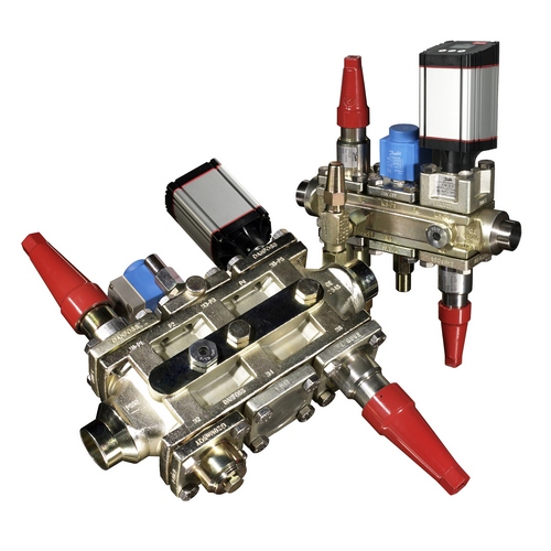
A pair of Danfoss ICF valve stations

The idea of all of these platforms is that you basically get a valve-station in a single valve body. The valves take up less room, require less welding, etc. I don’t have any arguments with any of that: my issue is how I am seeing them referenced on a P&ID and in SOPs.

Let me give you an example:

The valve we are going to talk about is a Danfoss ICF-32-6-3A. It is a fairly common configuration replacing a traditional liquid valve-train.

Schematic of the valve

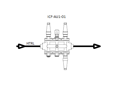
What I am seeing in the field is that this is represented in the field on the P&IDs as something like this:

Example1

In this situation, the entire compound valve is represented by a single tag. This results in SOP steps like this:

1) Close the liquid stop valve on ICF-AU1-01.

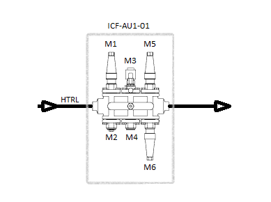
That step requires the operator to figure out which of the valves is the liquid stop valve. The correct answer is the first module or M1. We could write the stop to say so explicitly:

1) Close the liquid stop valve (Module 1) on ICF-AU1-01.

However, this step still requires the operator to identify the module. Most of the multi-valves have the Module (or port) number stamped on the valve but paint and insulation could get in the way of that.

What I would prefer to see is a more traditional valve labeling/tagging where each valve module/port is explicitly labeled/tagged. One way to do this while keeping with the same type of P&ID display is as follows:

Example2

This would let us change the SOP step to something like this:

1) Close the liquid stop valve on ICF-AU1-01-M1.

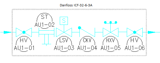
Of course, we could always reference each component of the valve with the more traditional names and tags such as :

  • HV-AU1-01 : Hand Valve (Stop in this case) on the air unit.
  • ST-AU1-02 : Strainer on the air unit.
  • LSV-AU1-03 : Liquid Solenoid on the air unit.
  • CKV-AU1-04 : Checkvalve on the air unit.
  • HXV-AU1-05 : Hand Expansion valve on the air unit.
  • HV-AU1-06 : Hand Valve on the air unit.

This might clutter up the drawing a bit, but something like this would be perfectly acceptable as well:

Example3

 Whichever method you choose, the performance basis is going to be what your operators understand. When introducing these new types of valves, a little bit of training and employee participation goes a long way!

Posted in General Information | Comments Off on Handling Compound Valve and Multi-Valve platforms in P&IDs and SOPs

$205,000 fine for dumping 40 pounds of ammonia

Kodiak fish processor North Pacific Seafoods pleaded guilty Tuesday in federal court to illegally dumping ammonia into the Kodiak city sewer, while the processor’s chief engineer faces charges of his own.
District Court Judge Ralph Beistline imposed $205,000 in criminal penalties, $55,000 of which should go to the city for “hazardous waste response training” and equipment for sewer and fire department employees, according to an Alaska U.S. Attorney’s Office press release.

Kodiak fish processor North Pacific Seafoods pleaded guilty Tuesday in federal court to illegally dumping ammonia into the Kodiak city sewer, while the processor’s chief engineer faces charges of his own.
District Court Judge Ralph Beistline imposed $205,000 in criminal penalties, $55,000 of which should go to the city for “hazardous waste response training” and equipment for sewer and fire department employees, according to an Alaska U.S. Attorney’s Office press release…

…According to Assistant U.S. Attorney Andrea Steward, the illegal disposal happened in late November 2011. Employees at Alaska Pacific Seafoods “dumped approximately 40 pounds of ammonia waste from its refrigeration system” into the sewer.

–Alaska Dispatch

That’s about $5,000 a pound! The article goes on to say that the chief engineer that directed the dumping is facing a charge for violating their DEC regulated permit.

Please make sure you have a plan in place to deal with Ammonia before you run the risk of finding yourself in this situation!

Posted in Community Involvement, Compliance, EPA, Incidents | Tagged , , | Comments Off on $205,000 fine for dumping 40 pounds of ammonia